Water system flow diagram
A water system flow diagram provides a schematic (simplified) representation of your facility’s water distribution system from the water meter or point of entry (to the facility) to points of use.
Scope
Flow diagrams are examples of concept diagrams used in many types of risk assessment to assist in identifying and understanding hazards (particularly exposures to hazards), hazard sources and hazardous events, as well as potential monitoring and control points within the water distribution system.
The flow diagram should capture the key components of your water distribution system. If it is too complex or too simple it will be of little use to your water risk management team.
It is not a plumbing plan for your facility, although if they are available, these plans may provide some useful information in compiling your flow diagram.
What should be in a flow diagram?
The information in a flow diagram should be represented in the order in which water travels through the facility from the point of entry to the site or building, to the outlets and note all connecting water lines, flushing points and direction of flow.
Individual points of use are not required, but a general description of the end use for each component must be provided, e.g ”patient bathrooms in Wards 1-5” or “laundry”.
Your flow diagram should clearly indicate the following key components, but not be limited to:
- all incoming water sources (e.g. town water supply, roof-harvested rainwater)
- any on-site cold water storages
- water heaters
- hot or warm water storages
- backflow prevention devices
- thermostatic mixing valves (TMV)
- main stopcocks (or stop valves)
- the fire suppression system
- the air cooling system, if cooling towers used
- return loops, especially for warm water systems
- areas of the facility serviced e.g. patient areas, irrigation, laundry
- any waste water disposal point that is not part of the main sewer.
Consistent symbols and legend should be used but it does not need to be to scale.
Depending on the size and the complexity of the water distribution system, there can be one or several flow diagrams.
While there are specialised programs available for drawing plans, the flow diagram can be developed using Word, Excel or PowerPoint.
Alternatively, the flow diagram can be drawn by hand and scanned or photographed to provide a digital copy.
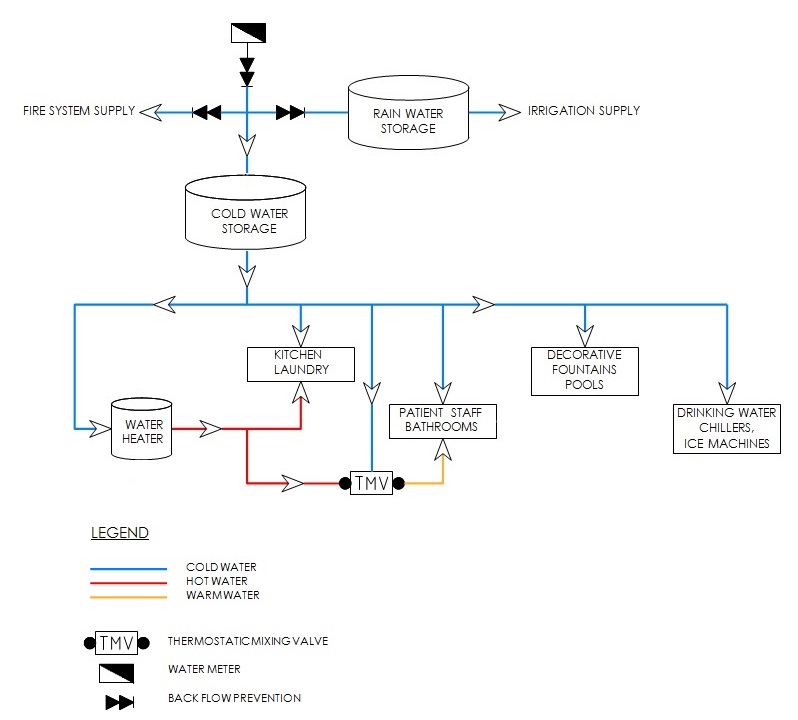
Example flow diagram